DISTRIBUTOR-FIRST SUPPLY PARTNER · SINCE 1999 Live · Pneumatic Automation System
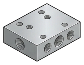
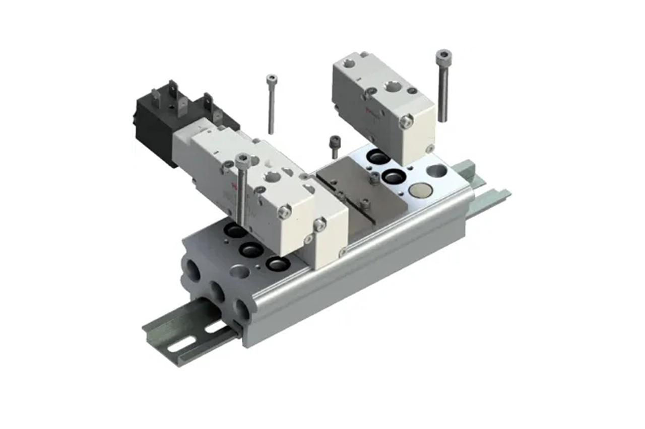
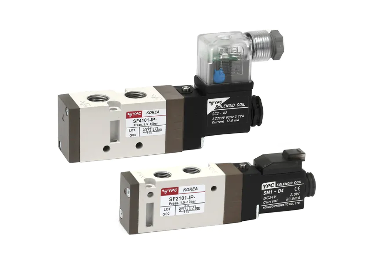
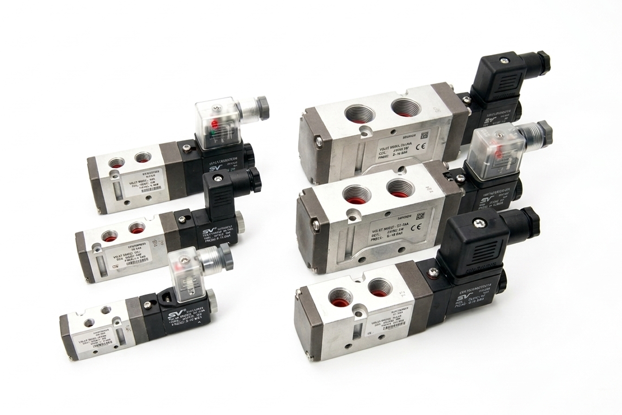
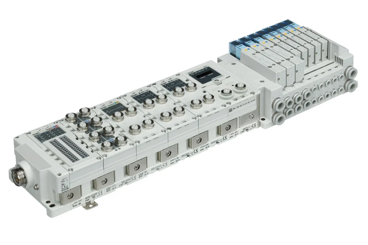
A manifold / sub-base valve is a directional control valve built to bolt onto a shared base that distributes one air supply and one common exhaust to every valve station. It is the standard construction for any machine running more than two or three cylinders — packaging lines, assembly cells, robotic systems — because individual loose solenoid valves stop scaling once the fitting and wiring count multiply. One supply line into the base, individual cylinder hoses off each station, and one or two shared exhausts. A single base mixes 5/2 single, 5/2 double, 5/3, and 3/2 stations side by side so one manifold serves a machine whose cylinders each behave differently.
Tips and pointers on when the sub-base manifold is the right call — and when to spec something else. Scroll the strip →
One supply line into the base feeds every station; one or two shared exhausts replace per-valve mufflers. Plumbing drops from 16 lines to one on a 16-valve machine; cabinet space shrinks roughly half.
D-sub or ribbon cable replaces 16 wire pairs — terminal count drops 80–90%. Failed station lifts off the base in seconds without disturbing supply, exhaust, or adjacent wiring. Service goes from "line down" to "swap and restart."
Bases built to the ISO standard accept valves from any conforming manufacturer. Any ISO-compliant valve swaps for another on the same base — no manufacturer lock-in, no re-piping. Mixed function codes (5/2 single, 5/2 double, 5/3, 3/2) on one base is standard.
Sum per-station Cv across all valves that can fire simultaneously — not per-station. Undersized supply causes manifold pressure droop on burst events; every cylinder slows together. Same logic for the shared exhaust. Plan 20% spare stations on fixed-length bases.
Manifold overhead doesn't pay back at that scale — base cost, mounting space, and shared-port plumbing exceed the value of consolidation. → Re-spec to inline solenoid valves below 3 cylinders.
A conventional manifold has no per-valve cycle count, no coil-current monitoring, no fieldbus integration — the diagnostic data is invisible. → Step up to IO-Link valve terminal. Same ISO base can field-upgrade later by swapping the gateway module.
Hazardous-area manifolds exist but are uncommon — most ATEX installs are inline single valves at each cylinder. → Re-spec to ATEX solenoid for each cylinder station in a Class/Division or ATEX-zone area.
From the machine spec sheet to the part number. Answer what you know, leave the rest blank, and send.
Pick the priority; the quote desk handles the cross-reference.
The manifold conversation is the labor-savings conversation. The customer is not buying valves; they are buying a wiring loom, a plumbing diagram, and a service plan that costs less.
Each industry below uses this product across the listed areas. Open an industry to see how it fits the rest of its system.
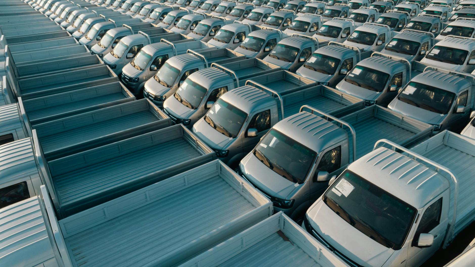 Automotive Manufacturing →
 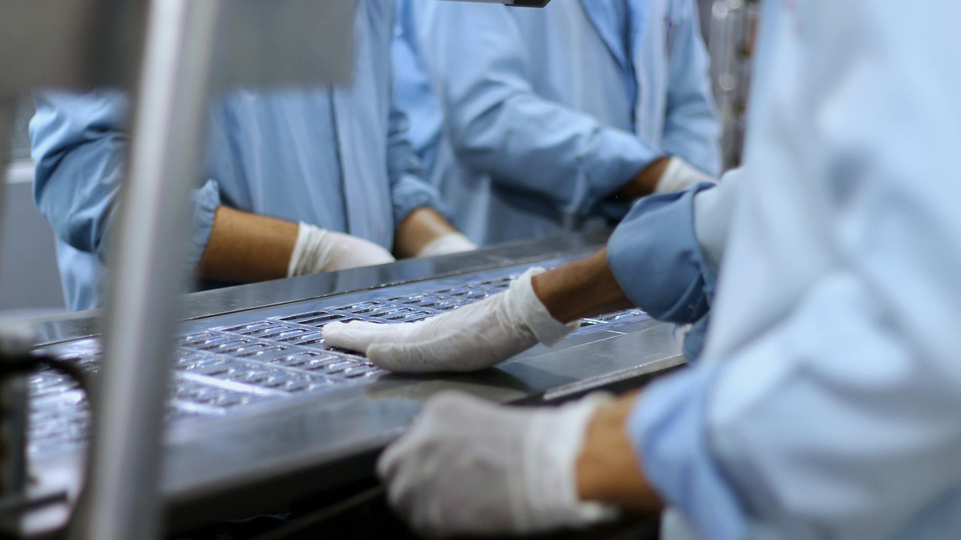 Pharmaceutical, Medical Device & Laboratory →
 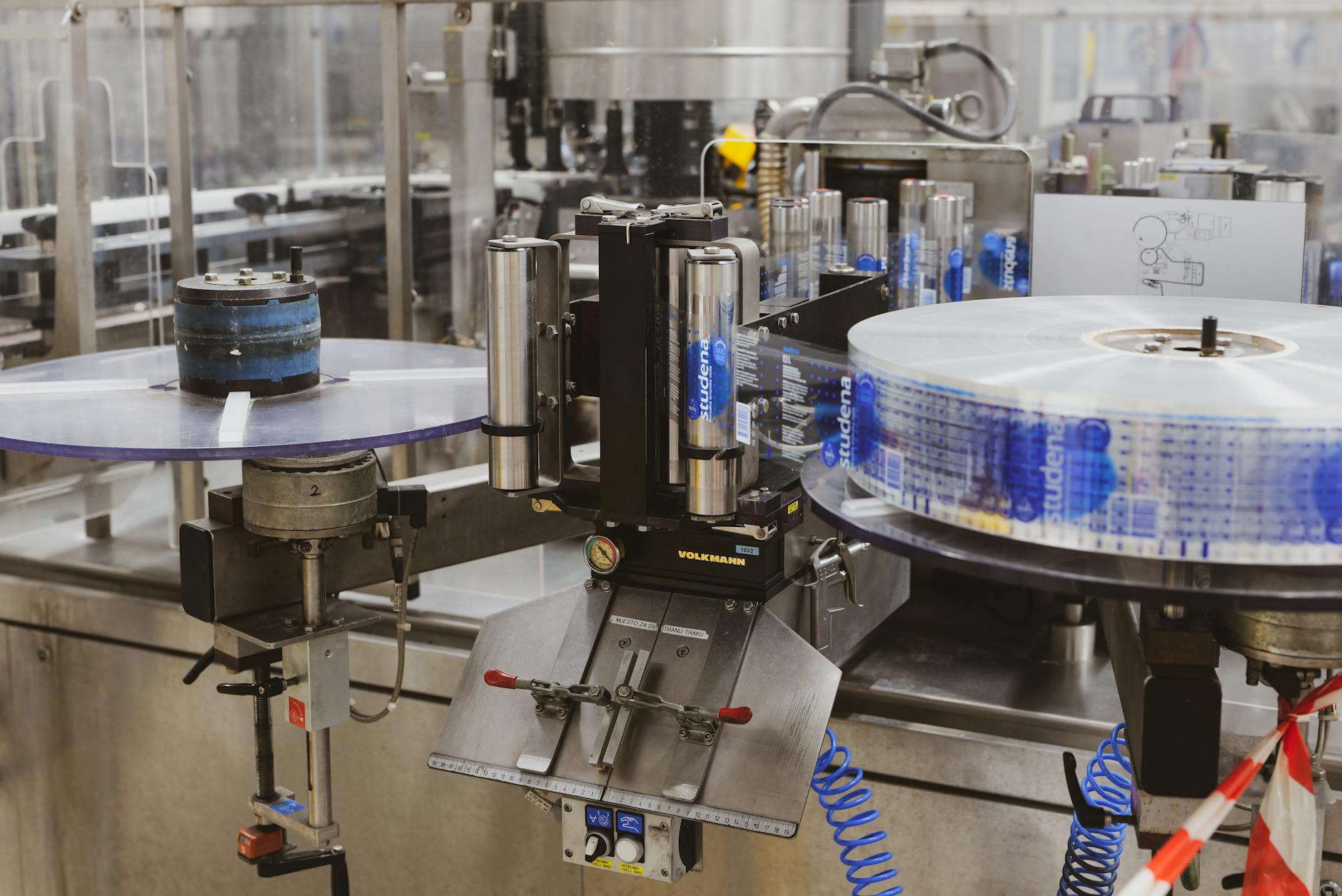 Packaging & Printing →
 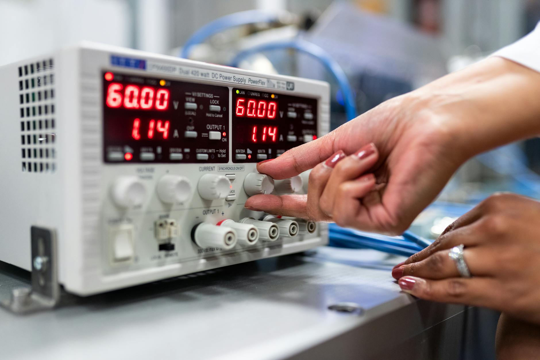 Electronics & Semiconductor →
 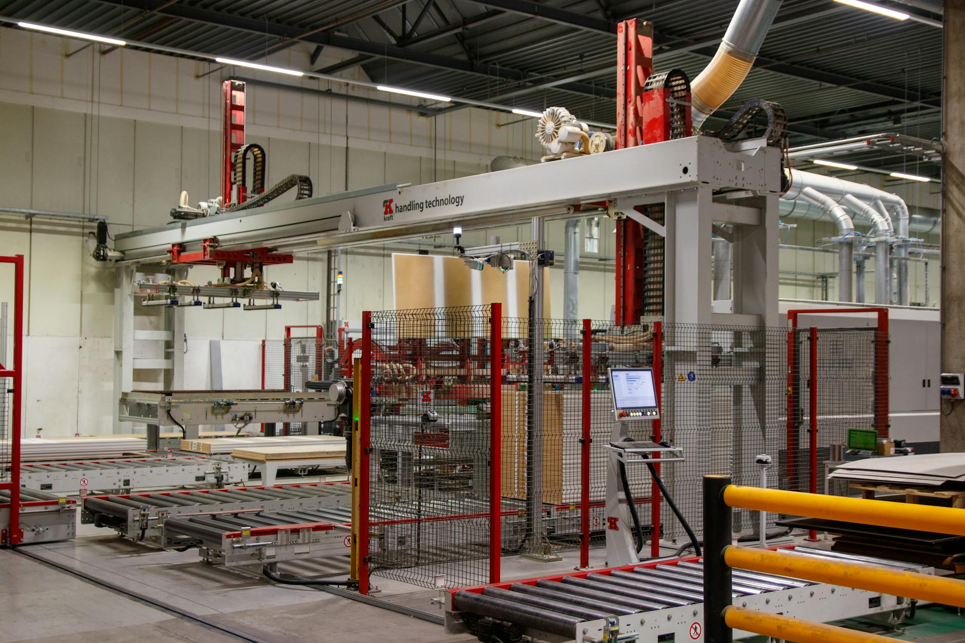 Material Handling & Conveyors →
 Also applies to OEM automation — the standard for multi-cylinder machines. · Existing machine modernization. · Test stands and lab equipment.
Every entry is a real product on this site — linked, not just named. Quote them on the same line item.
Stock one spare valve per function code on the manifold for the high-criticality station population. Failed valve lifts off the base in seconds, spare drops in, machine back in service — no waiting for shipping. One 5/2 single, one 5/2 double, one 5/3 closed-center covers most installs.
Send us the application — a specialist routes you to the correct tier with a configured part. Lead-times and pricing returned within one business day.
—. We reply within one business day with pricing, lead-time, and configured parts.