DISTRIBUTOR-FIRST SUPPLY PARTNER · SINCE 1999 Live · Pneumatic Automation System
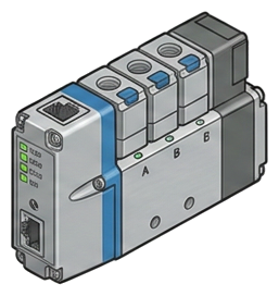
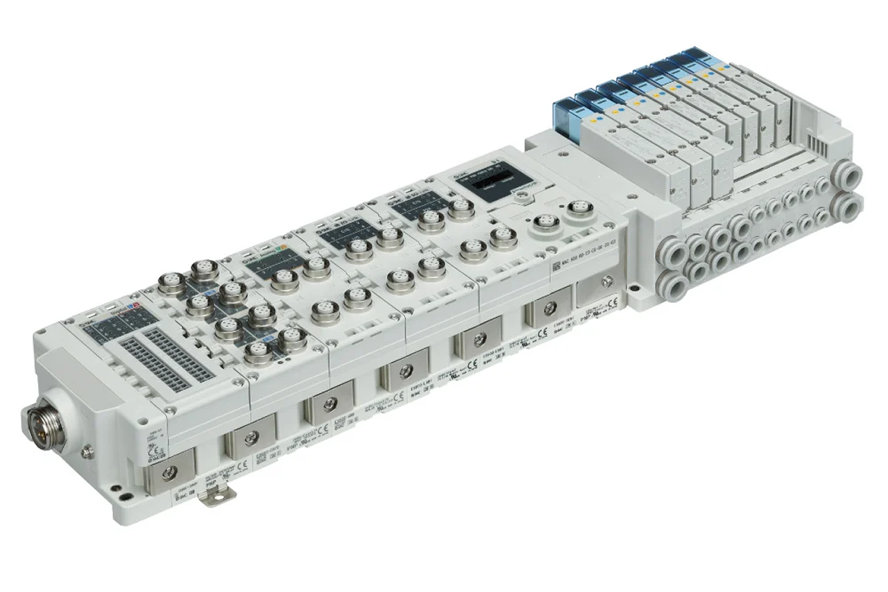
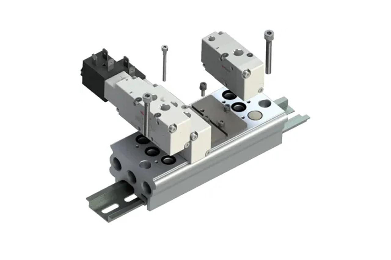
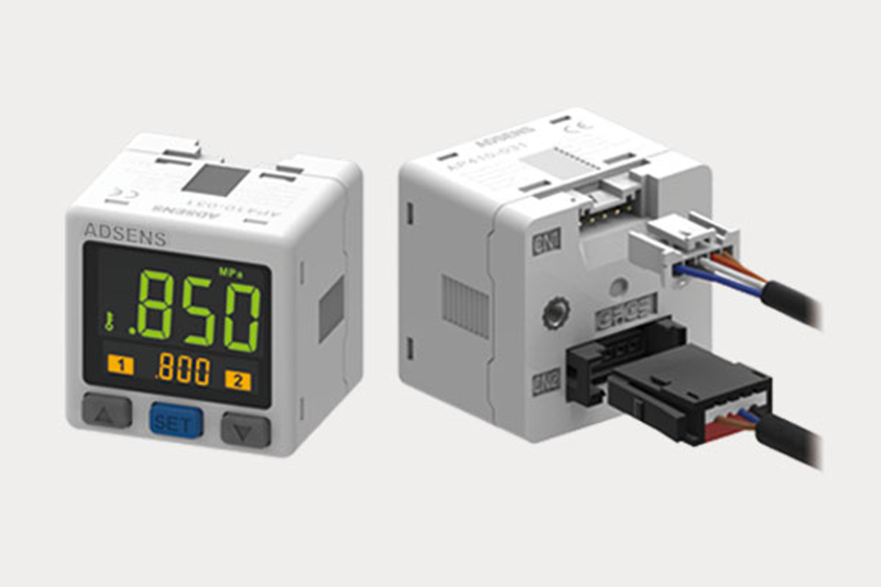
An IO-Link valve terminal is a smart valve manifold — multiple solenoid valves on one base with a single network gateway that reports data while routing air. Several stations mount side-by-side, share an internal supply and exhaust, and connect to the PLC (the machine's programmable logic controller) over one fieldbus cable instead of one wire bundle per valve. The gateway streams continuous diagnostics — per-valve cycle count, valve state confirmation, solenoid coil current, supply voltage health, manifold temperature — into the PLC, the SCADA, the MES, or a historian. This is the bridge component between traditional pneumatics and Industry 4.0 / IIoT (Industrial Internet of Things): the right answer whenever a customer is moving toward a smart factory, predictive maintenance, or remote diagnostics — and equally valid as a pure wiring-reduction play on a machine with many valves.
Tips and pointers on when the IO-Link valve terminal is the right call — and when to spec something else. Scroll the strip →
A conventional 16-valve manifold runs a 32-conductor bundle to the PLC. The IO-Link gateway collapses that to a single 3-wire IO-Link cable or one industrial Ethernet line — large immediate labor savings on fresh installs, larger on retrofits.
Cycle count, shift confirmation, coil current, supply voltage, manifold temperature, downstream pressure where integrated. Maintenance sees a valve approaching its cycle-life rating weeks before failure — replace on the next scheduled changeover, not during an unplanned line stop.
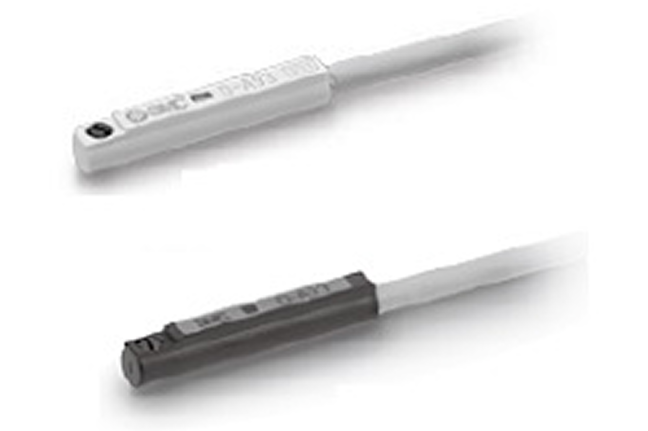
The same gateway hosts IO-Link sensors and switches — vacuum, pressure, position. One network, one cable, one diagnostic feed for valves and sensors combined. Each added endpoint compounds the original deployment.
The gateway is firmware-locked to ONE protocol. EtherNet/IP for Allen-Bradley / Rockwell, PROFINET for Siemens, EtherCAT for motion-heavy machines, DeviceNet / Modbus TCP for legacy. Get the confirmation in writing from the controls engineer — Rockwell plants sometimes run PROFINET on inherited Siemens lines.
IO-Link is not a substitute for safety pneumatics. Applications requiring ISO 13849 PLd or PLe need dedicated rated hardware. → Route safety-rated functions through the customer's safety engineer; IO-Link handles standard automation only.
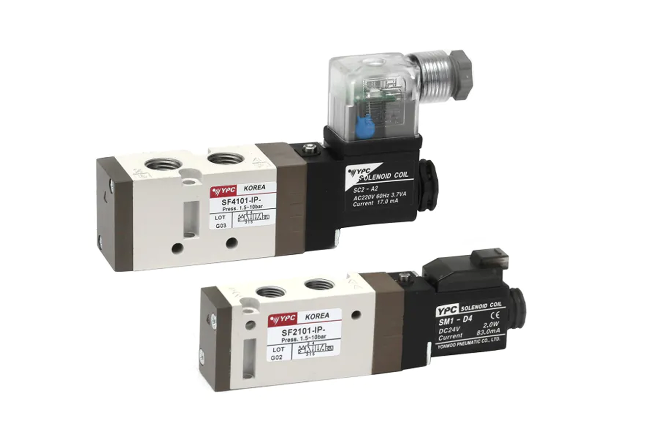
Gateway and terminal overhead doesn't pay back below roughly 8 valves on one machine. → Re-spec to inline solenoid valves for one- or two-valve installs where wire-bundle savings can't justify the gateway cost.
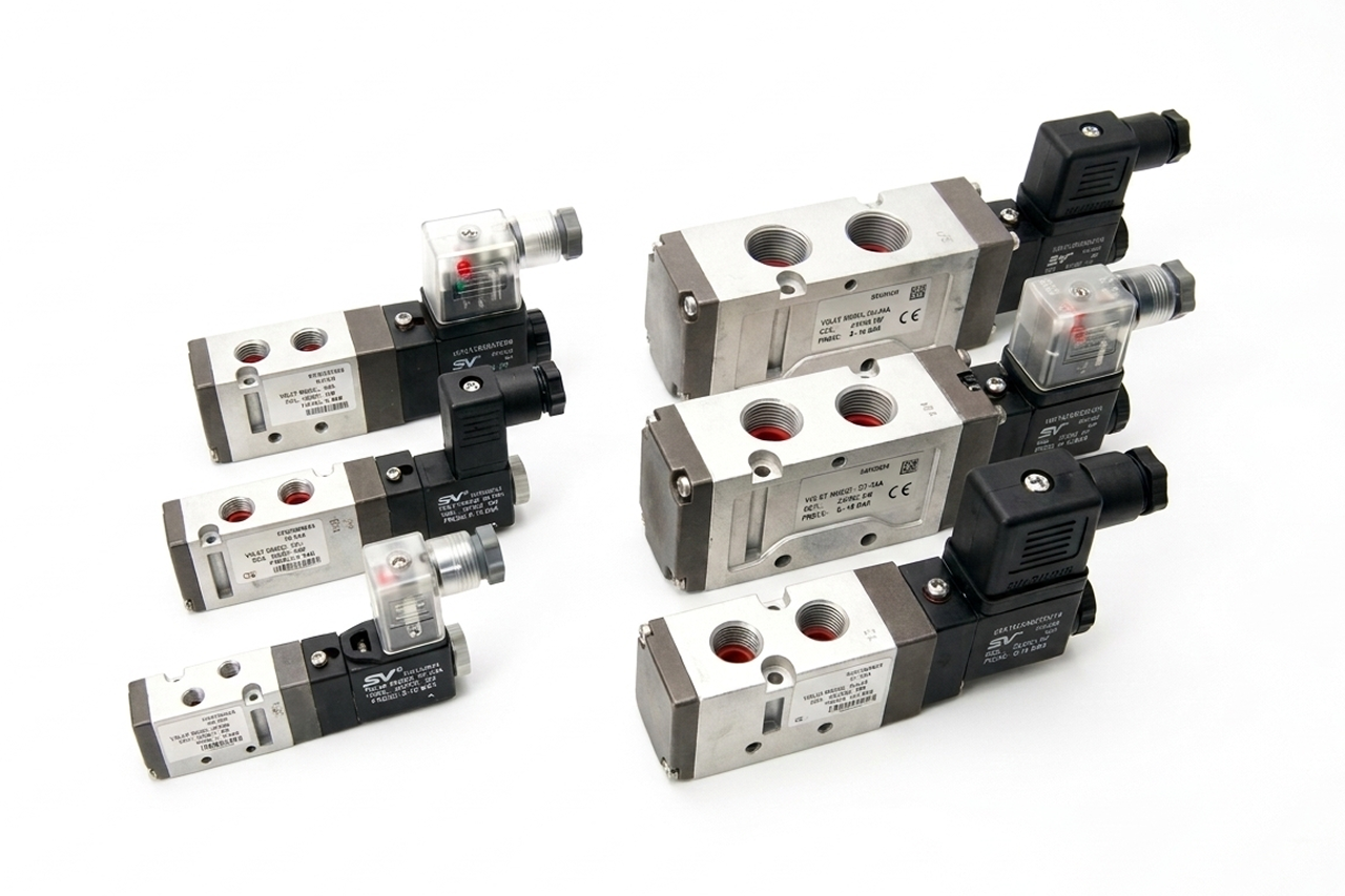
If the customer isn't doing predictive maintenance, MES integration, or cloud monitoring AND isn't buying on cable-savings, the diagnostic value goes latent. → Re-spec to manifold sub-base valve on the ISO 5599/15407 standard so a gateway-module swap can field-upgrade later.
From the machine spec sheet to the part number. Answer what you know, leave the rest blank, and send.
Pick the priority; the quote desk handles the cross-reference.
The IO-Link conversation has two doors. Door 1 is wiring-savings on a multi-valve machine — anyone can buy that case. Door 2 is the predictive-maintenance program — only customers with a real IIoT initiative buy that case, but they buy it big.
Each industry below uses this product across the listed areas. Open an industry to see how it fits the rest of its system.
 Automotive Manufacturing →
  Pharmaceutical, Medical Device & Laboratory →
 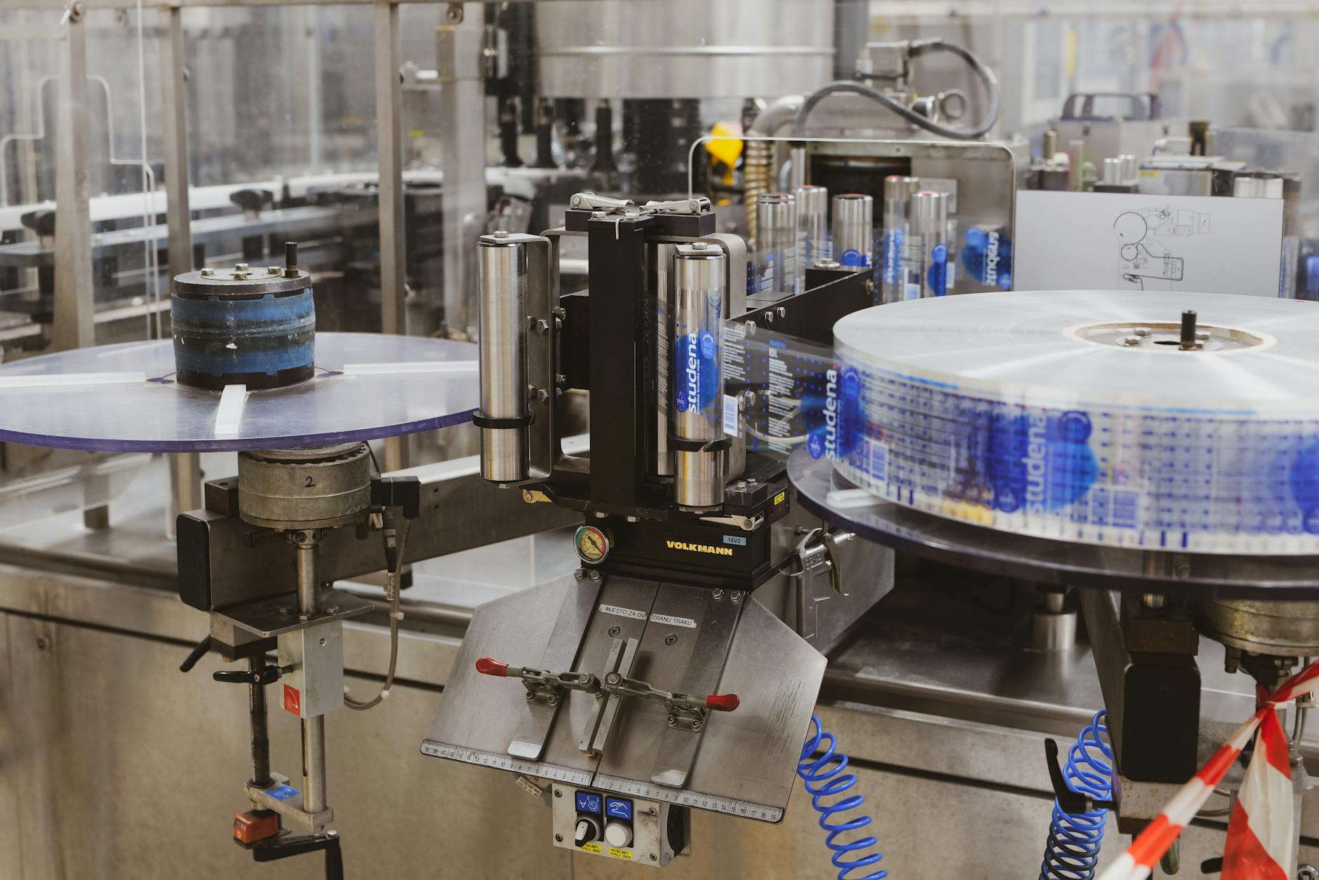 Packaging & Printing →
  Electronics & Semiconductor →
 Also applies to Existing-machine retrofits · Bridge-to-IIoT pilot deployments
Every entry is a real product on this site — linked, not just named. Quote them on the same line item.
IO-Link terminals are per-machine engineered orders, not bulk SKUs — station count, protocol, IP rating, and configuration vary by machine. Bulk-volume buys instead in the surrounding accessories: industrial Ethernet cable (pre-terminated for the gateway's protocol), 24 VDC power supplies sized to the coil count, and seal-kit / replacement-part inventory for the valve stations. The terminal itself is configured once per machine and replaced rarely.
Send us the application — a specialist routes you to the correct tier with a configured part. Lead-times and pricing returned within one business day.
—. We reply within one business day with pricing, lead-time, and configured parts.